

This article builds on our understanding of flame detection technologies discussed in issues 761 and 782 of this magazine by discussing a real-world application. Large Atmospheric Storage Tanks (LASTs), also called “day tanks typically have diameters of up to 100 metres (330ft)3.
Multi-spectrum IR (IR3) flame detectors – which are the type most often installed in oil and gas facilities – typically apply a range of 30m (100 ft) under ideal conditions when using a 1 ft2 n-heptane pool fire, the standard test fire used in FM3260 testing. Desensitizing environmental factors, interference sources and dirty optics significantly shortens this range. The extent to which the detector is expected to be desensitized can be calculated using test values from the detector’s FM3260 report and a well-established formula with broad acceptance in the industry.4,5
When determining the effective viewing distance of a detector, for an oil and gas / chemical facility, we see performance is reduced to approximately 60% of the ideal range (18 m), although this can be optimistic for some IR3 detectors.
Many IR3 units have higher sensitivity settings that achieve detection distances, to a 1 ft2 n-heptane pan fire, of 60-80m. It should be noted however, that optical flame detectors are normally expected to have a mean time to detection (MTD) less than 10 seconds. At higher sensitivity settings, some units have MTDs of 17 to 22 seconds and an effective viewing distance range of typically 36-40m. Whichever sensitivity setting is used, care must be taken to ensure the product is configured correctly.
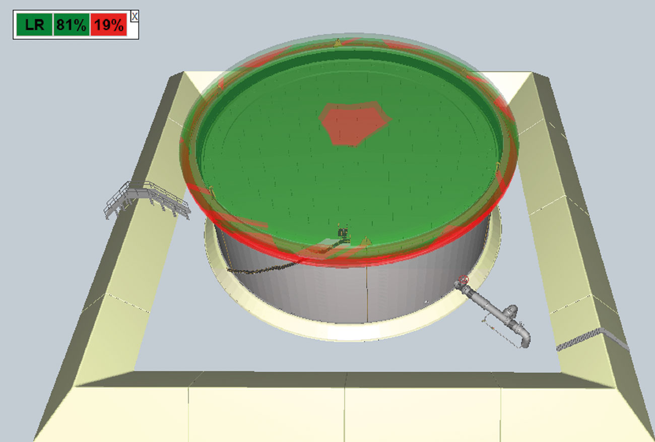

When the detectors are not capable of “seeing” the target fire across the full diameter of the tank, it is recommended that the detectors be rotated to look around the edge of the tank rim. An example of this, using a layout with six IR3 detectors, can be seen in figure 1 below.
Figure 2 shows the assessment results obtained with the layout in figure 1 with a 250 kW RHO target fire size. This six-detector layout achieves complete coverage of the rim seal although there is a coverage gaps in the middle of the tank roof. As fires are not really expected in this area, so this gap in coverage is not concerning.
It’s worth noting that additional detectors would need be deployed to cover larger tanks or smaller target fire sizes.
In 2011, an independent review on loss prevention by FM Global6 recommended that visual imaging flame detection systems be applied as the default technology in outdoor industrial applications.
Intelligent Visual Flame Detectors have been used since the late 1990’s. iVFD detectors employ a video imaging-based technique utilising a CCD array and advanced algorithms that process live video images for flame like characteristics. More recent developments use dual CCD arrays with one array being exclusively used for flame detection whilst the other offers a live video feed.1
iVFD’s monitor for bright burning fires, the limitation with the technology is that it cannot invisible or virtually invisible fires such as pure methanol or hydrogen.
It is worth noting that, while both IR3 or iVFD detectors are capable of achieving complete coverage of the rim-seal for any size of tank using this approach to layout design, on larger tanks, the number of IR3 detectors required to achieve complete coverage will be larger than the number of iVFDs required, owing to the superior effective viewing distance that the iVFDs achieve in the field.
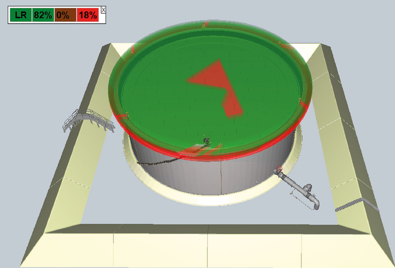
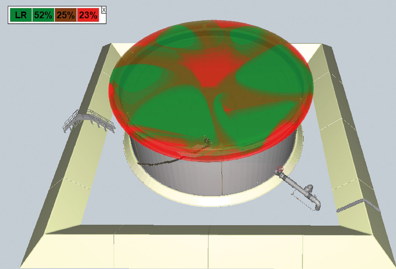
To illustrate this point, Figures 3 and 4 show the coverage achieved for a smaller target fire size (100 kW RHO) using just three iVFD layout shown. By way of comparison figure 5 shows a design using IR3 detectors for the equivalent fire size. The results clearly show that, using the same target fire size (100 kW RHO), the iVFDs can provide superior coverage using 50% fewer detectors.
When developing the layout using optical flame detectors one final important consideration needs to be addressed, namely that the design must be suitable for the floating roof extents, all the way up and down. Coverage can be modeled and verified by employing 3D Fire and Gas mapping software that uses the unique detection characteristics (field of view, sensitivity and effective viewing distance) of the detectors to be used.
Summary
This article has shown that different optical flame detectors can be used to achieve complete coverage of the rim-seal of a LAST. The number of detectors needed will depend on the size of the tank, the specified target fire size for detection, and – most importantly – the type of detector used. When using the effective viewing distance calculation, it can be seen that fewer visual flame detectors are needed for the same target fire size.
For more information, email info@micropack.co.uk
References
- Duncan, Graham. International Fire Protection magazine issue 76, pages 72-74.
- Sizeland, Eliot. International Fire Protection magazine issue 78, pages 29-30.
- Duncan, Graham; McNay, James. “Restoring Fire Detection Confidence: The use of visual flame detection equipment can provide operators with a proven and comprehensive early warning system. Available at: <http://micropack.co.uk/images/downloads/Micropack-Visual-Flame-Detection-Tank-Storage.pdf>.
- McNay, James. “Desensitisation of Optical Flame Detection in Harsh Offshore / Onshore Environments.” Proceedings of the 70th Annual Instrumentation Symposium. Jan 2015. Texas A&M University. College Station, Texas.
- McNay, James. “Desensitisation of optical based flame detection in harsh offshore environments.” International Fire Professional. July 2014. No. 9. 12-14.
- FM Global Property Loss Prevention Data Sheets 5-48
- Pittman, William. Scoggins, James. Application of Visual Flame Detection and Hazard Mapping to Large Atmospheric Storage Tanks. Proceedings of the 19th Global Congress on Process Safety. AIChE. New Orleans. March 31 – April 4, 2019.
About the Author
Written by William Pittman Ph.D. Senior Fire and Gas Detection Consultant. Micropack Detection Americas.

You must be logged in to post a comment.